Introduction
A few months ago, while browsing a computers auction store as usual I noticed a $1 reserve server blade – the HP BL460c Gen 8, with two E5 2640 v2 CPUs. That looks like a good deal to me!
I got to know about blade servers when I was looking at getting some cheap hardware for creating Chia plots a few months back. Here is a Wikipedia link describing them. Basically, they’re a stripped-down computer system with only the processor, RAM, and a minimal number of hard drive slots. Power, cooling and communications are all provided by the chassis (also known as the blade enclosure), which can host multiple server blades as well as other blade modules for storage, networking, etc. This can greatly increase the amount of computing power that can fit in a rack as the power supplies and cooling infrastructure are shared. It also means that the enclosure is very expensive, heavy, noisy, and power-hungry.
Since the server blades are such specialised hardware, they’re believed to be useless without the chassis and are sold for cheap. Some people on YouTube did manage to get some old blades to start without the chassis, but I didn’t see any with the BL460c Gen8, and I wasn’t sure what’s involved in figuring it out. So my initial thoughts were just to buy it for the processor as I was hoping to upgrade the CPU for my desktop PC, the Dell T3600. (Well, I later found out the T3600 doesn’t support v2 CPUs, but that’s okay)
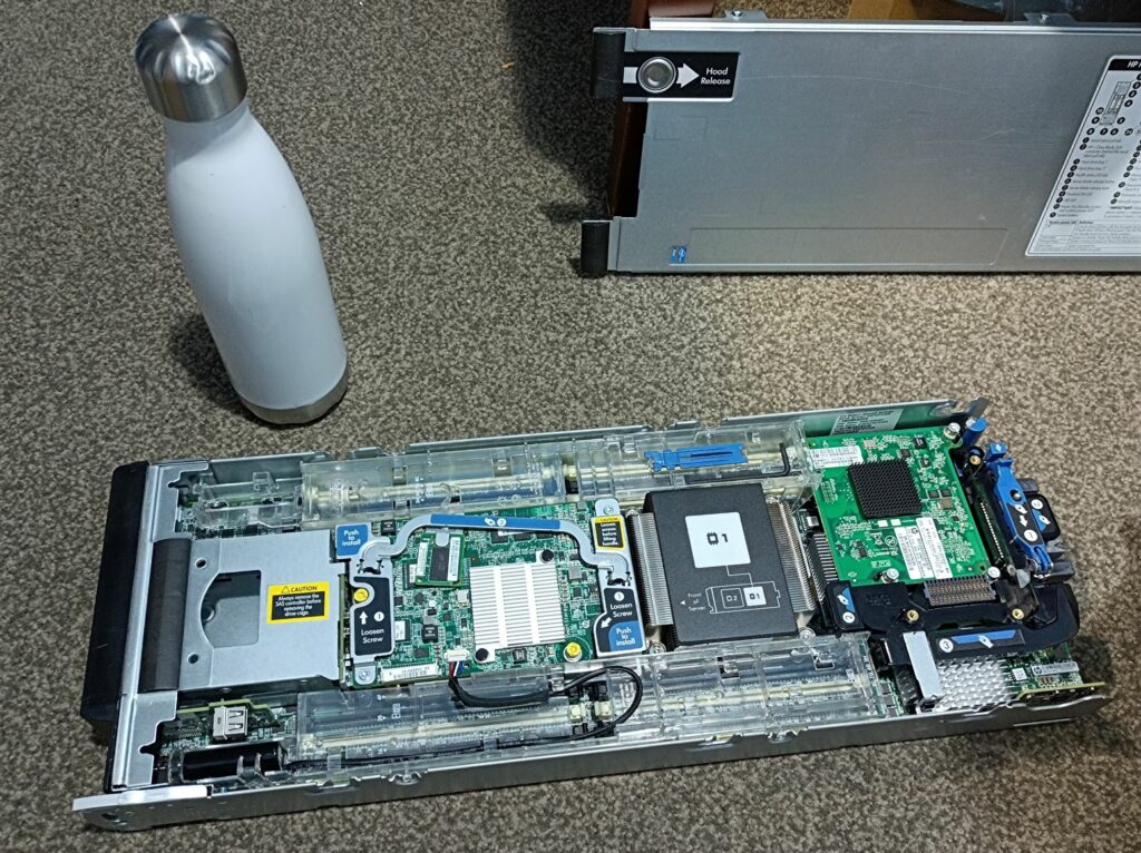
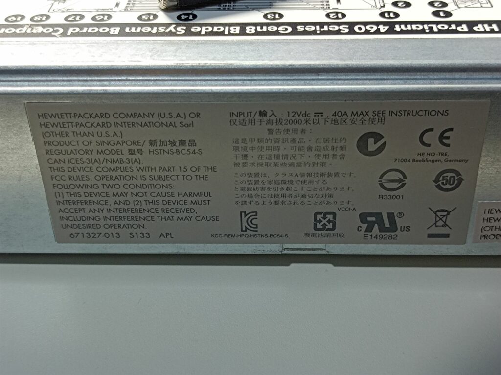
I ended up getting this for $12, and later two more at similar prices ($16 and $25). Here’s a photo of the blade with its lid off, a close-up of the proprietary backplane connector and the side label:

The blade also came with a 2-port 8Gb fiber channel HBA card (QMH2572, part number: 659822-001) and an onboard network card (FlexibleLOM 554FLB, part number: 647584-001). These cards plug into the also proprietary mezzanine PCIe slots on the motherboard and provide communications via the backplane connector to the enclosure. Here are some photos of the cards:
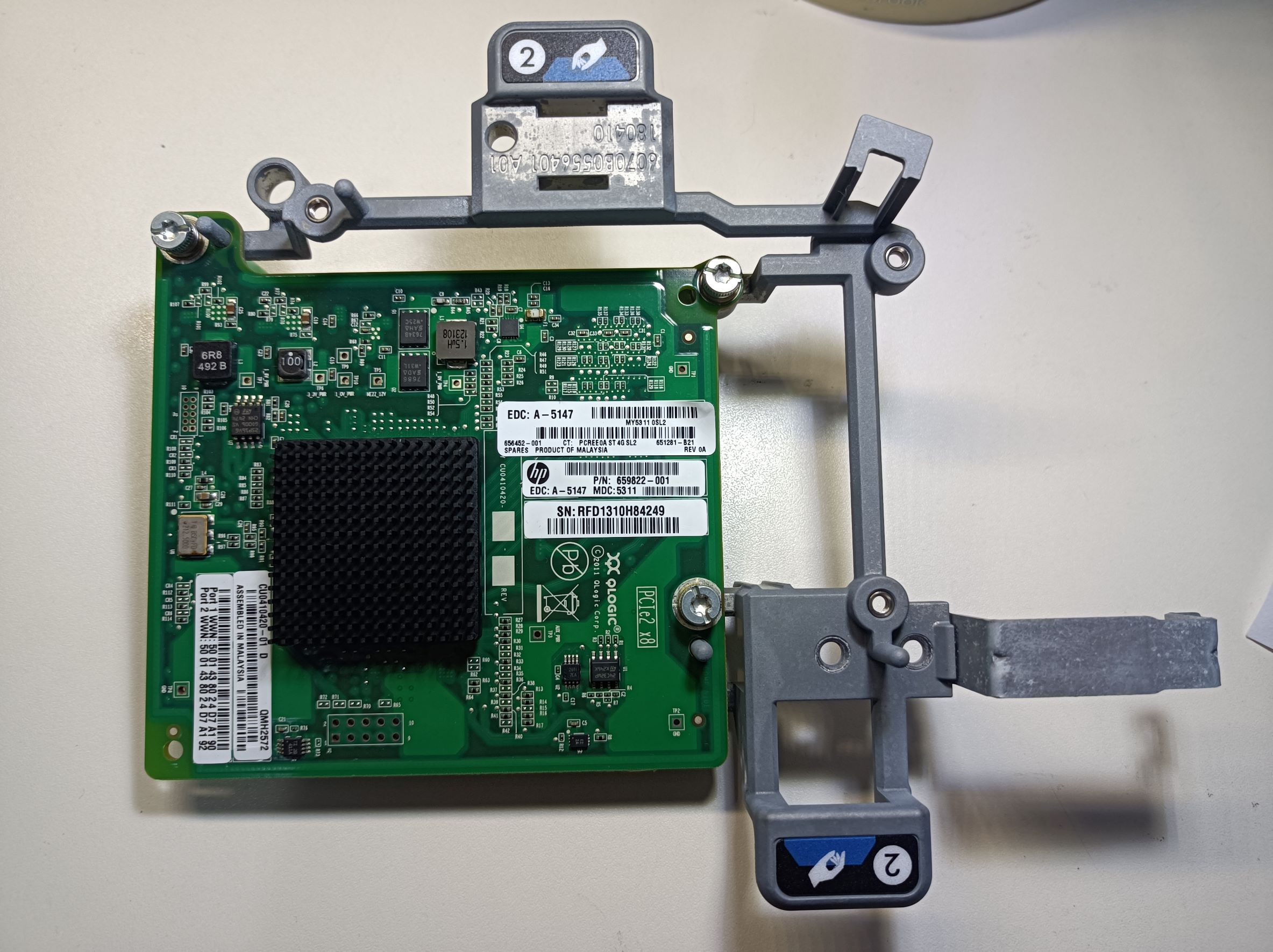
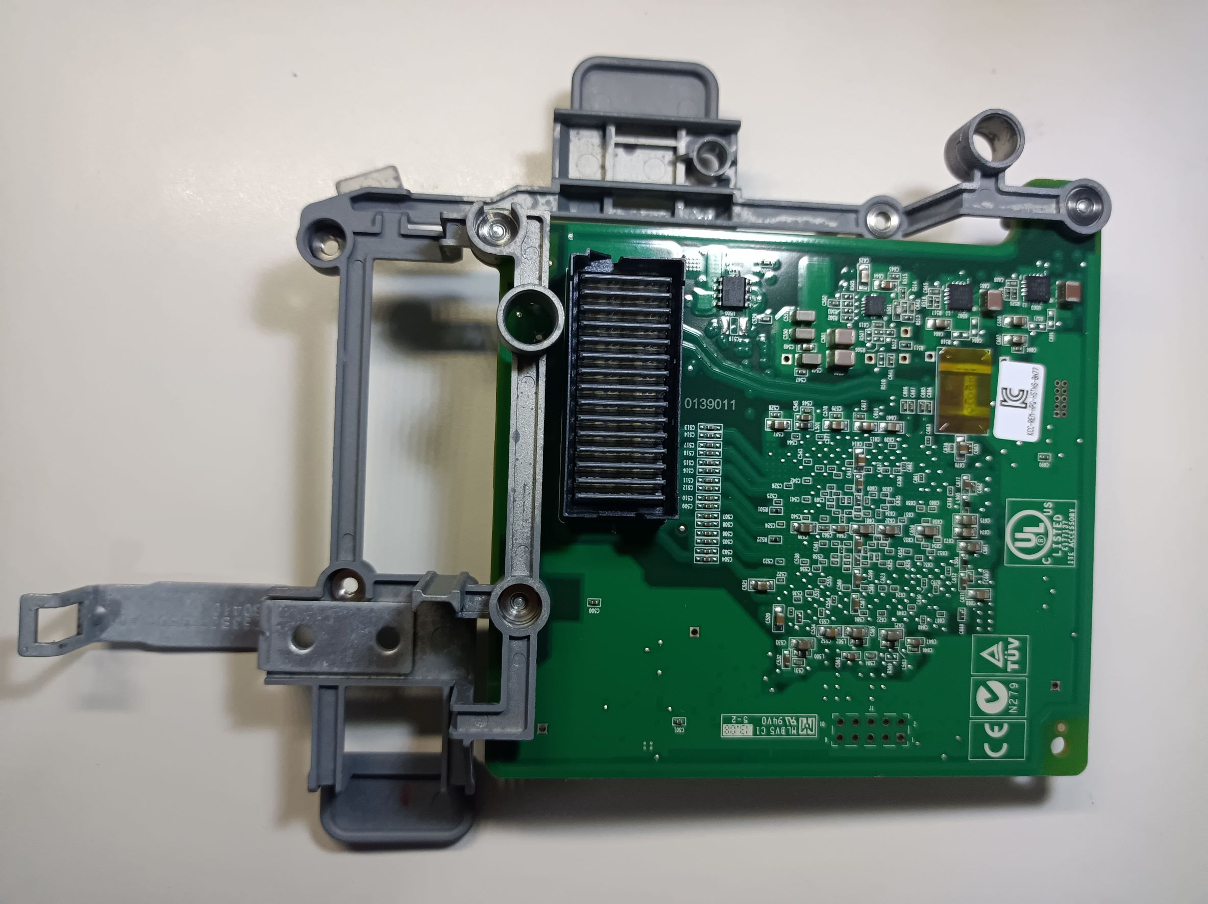
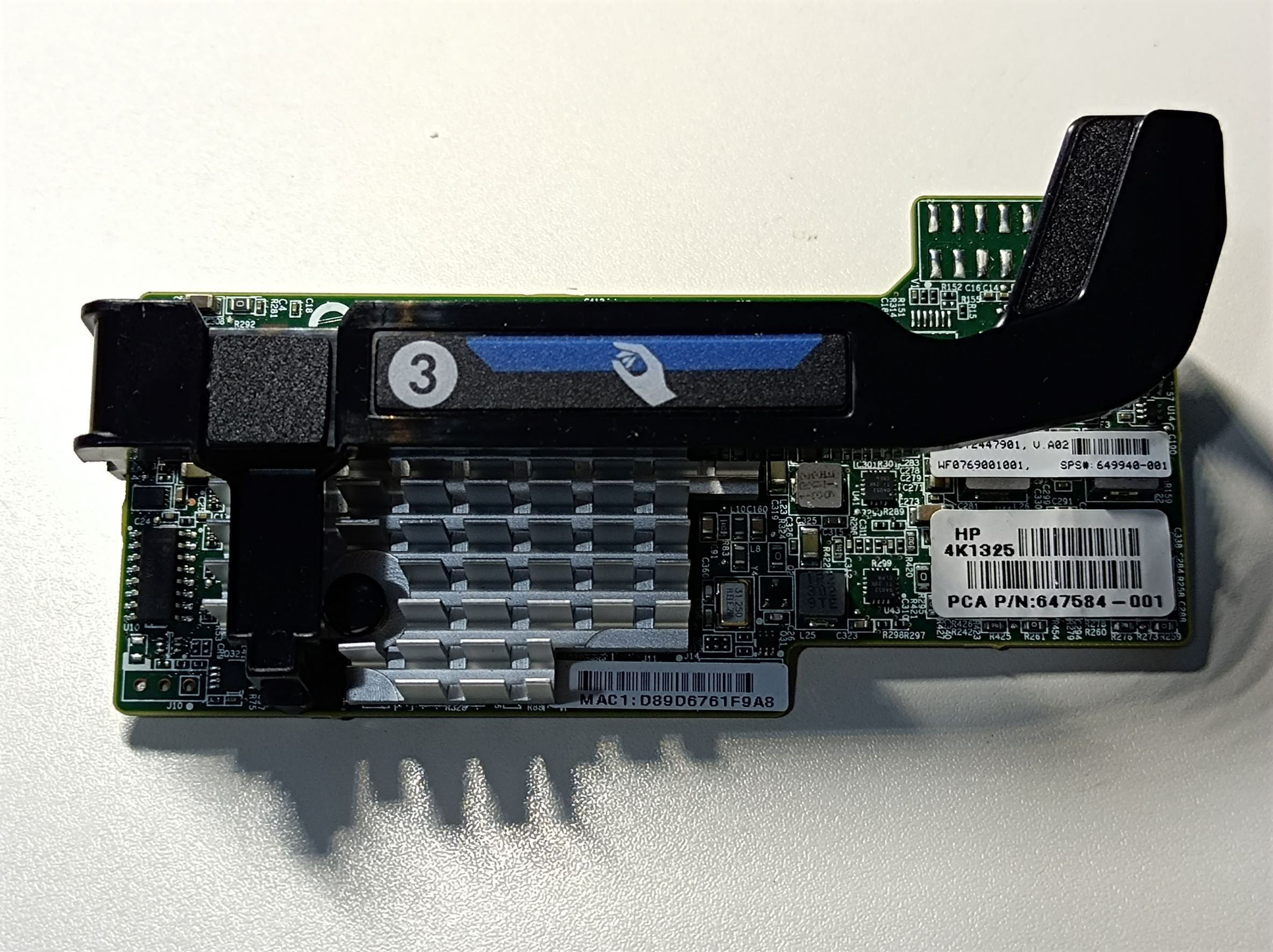
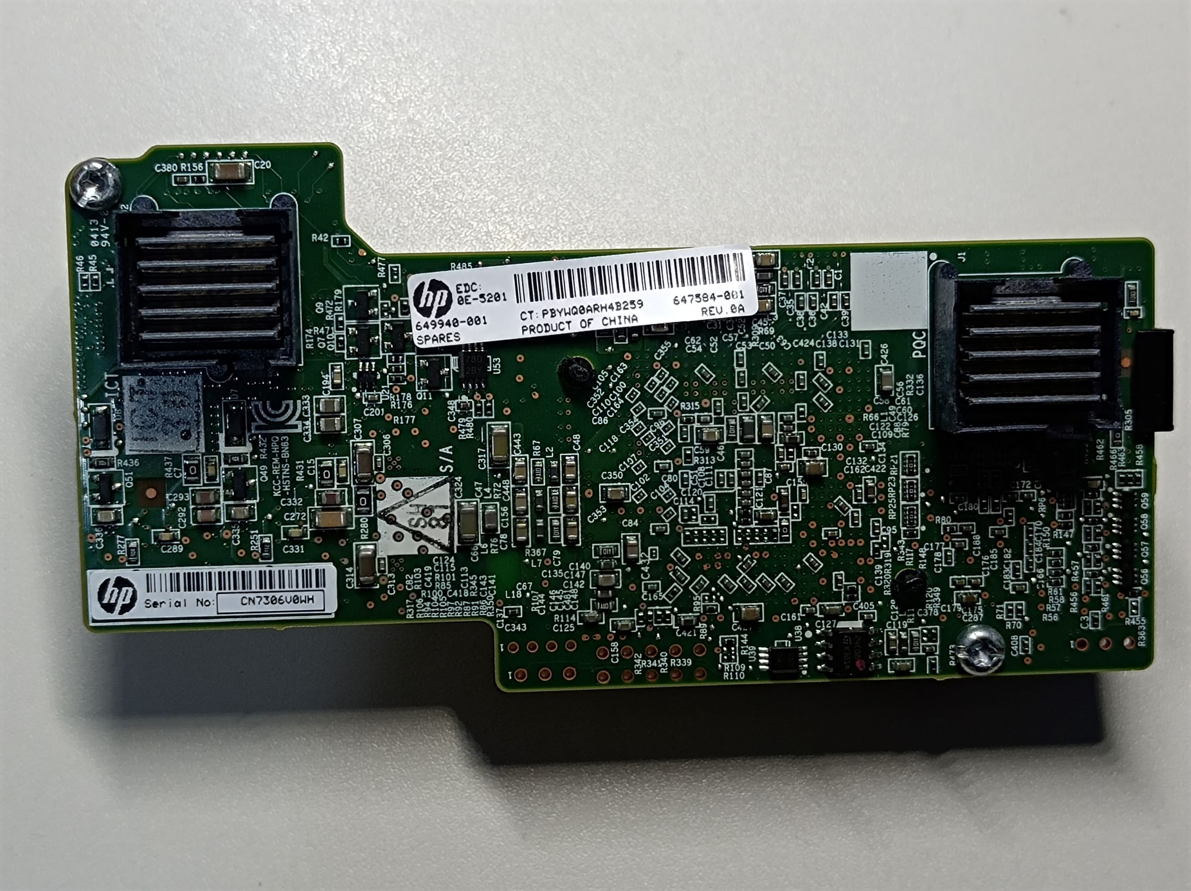
In Ubuntu 20.04, the 8Gb FC card is recognised as two “QLogic Corp. ISP2532-based 8Gb Fibre Channel to PCI Express HBA (rev 02)” devices, and the NIC card is recognised as eight “Emulex Corporation OneConnect 10Gb NIC (be3) (rev 01)” devices.
Once I found out that I couldn’t use the E5 v2 CPUs in my T3600, I started exploring ways to make this server work without the chassis. Something like this could be quite nice for simulation software or video editing, where the software can use the many CPU cores and single-core performance isn’t too important.
Generally, to use the blade server without a chassis, there are a few problems to solve:
- Power supply (in this case, 12V DC and up to 40A)
- Cooling (the blade server has no fans)
- Actually getting the server to start without a chassis
- Getting the display output to a monitor (maybe not required if running headless)
- Connectivity (Ethernet, USB, etc.)
Power Supply
The power is supplied to the server by two sets of high-current sockets on the back, which happen to fit standard 4mm banana plugs quite well (again, learned this from another YouTube video 😀 ). The two sets are in parallel and only one set needs to be connected. The top sockets are connected to GND, and the bottom sockets are +12V. In initial testing, I used a bench power supply set to 12.5V output, with the extra 0.5V compensating losses in the cables and the connectors. If I set the supply to output 12.0V then I would get brown-outs during startup. In the following image, I used a power supply lead for temporary testing, which worked well:

The latter two servers I got have a slightly different part number (655492-003 instead of 655492-004), and they were equipped with E5 2620 CPUs instead of the 2640v2. Oh well, the CPUs don’t worth much anyway… Despite both being BL460 Gen8, there are some minor differences between the model with the suffix -003 and the -004, with the most notable being the power jacks on the -003 are actually a little smaller than the ones in the -004, and some 4mm banana plugs may not fit.
When making the power cables, I only had some of the cheap banana plugs that have loose springy contacts, which would have higher contact resistance. I tried to spot weld them to the center rod but eventually resorted to just soldering them, which worked okay. For connecting to the wires, instead of the screws I simply soldered the wires to the plugs to ensure a good, low resistance connection.
During boot, the server drew the most power in the “power and thermal calibration” stage, which was about 14A, as shown below. Obviously, this depends on what CPU is equipped, what RAM is installed, etc. Based on the power supply readings, the idling power draw of the server is about 80W.

Once I’ve managed to get the blade server to work and boot Ubuntu, I got a server power supply out of my old servers collection:
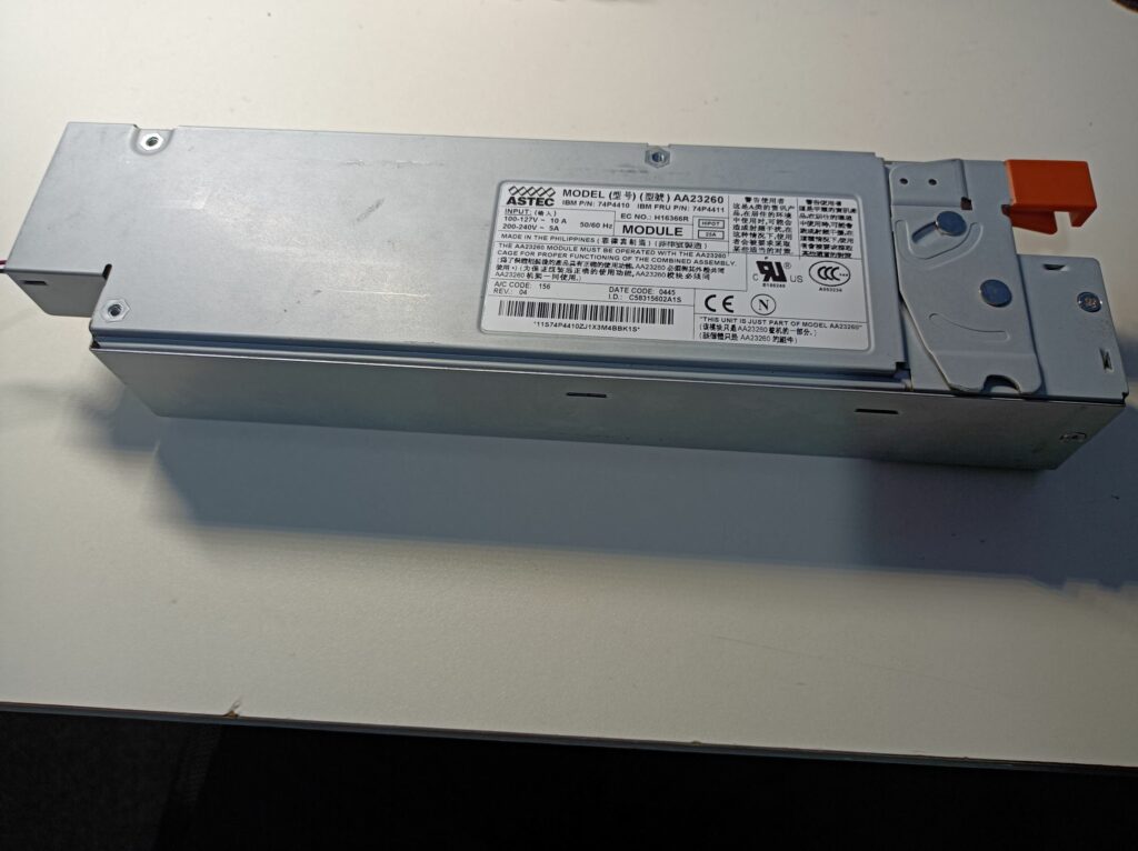
The power supply has a model number AA23260 and is made by Astec. Although there are no markings of its output rating on the supply itself, I found this information on the assembly this supply plugs into. This module contains converters that generate the 5V and 3.3V rails from the 12V, so the power supply is likely rated for some 52A at 12V if I work it backwards from the 625W rating. The blade server is rated for 40A so this should work.

Starting server power supplies are usually fairly simple – there should be a few control pins that turn on the supply when they’re pulled down to GND. Here’s a photo of its output connector:
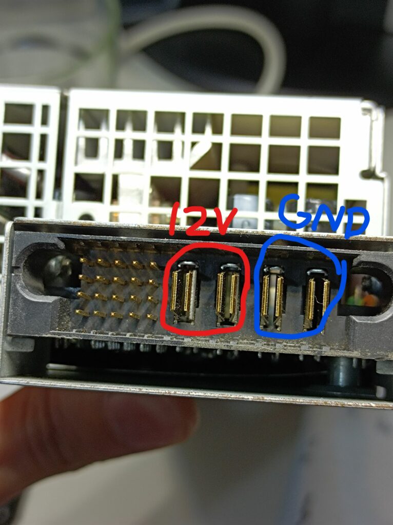
For this power supply, I happened to find an old forum post documenting its pinouts here and the steps taken to find them. Here’s a reproduced pinout table:
| – | 12V | – | 5V SB | 5V SB |
| GND | 5V | – | – | – |
| PSON | PSKILL | – | – | – |
| – | – | – | – | – |
For this power supply, pulling the PSON and PSKILL to GND with 1K resistors successfully turned it on, and the output voltage was measured to be 12.2V. I then connected the main outputs to the blade server and it worked! Although it’s worth noting that at this high current, thick gauge wires are required to keep the voltage drop on the wires minimal, or the server may report power supply faults at high loads. I used 18AWG wires.
Cooling
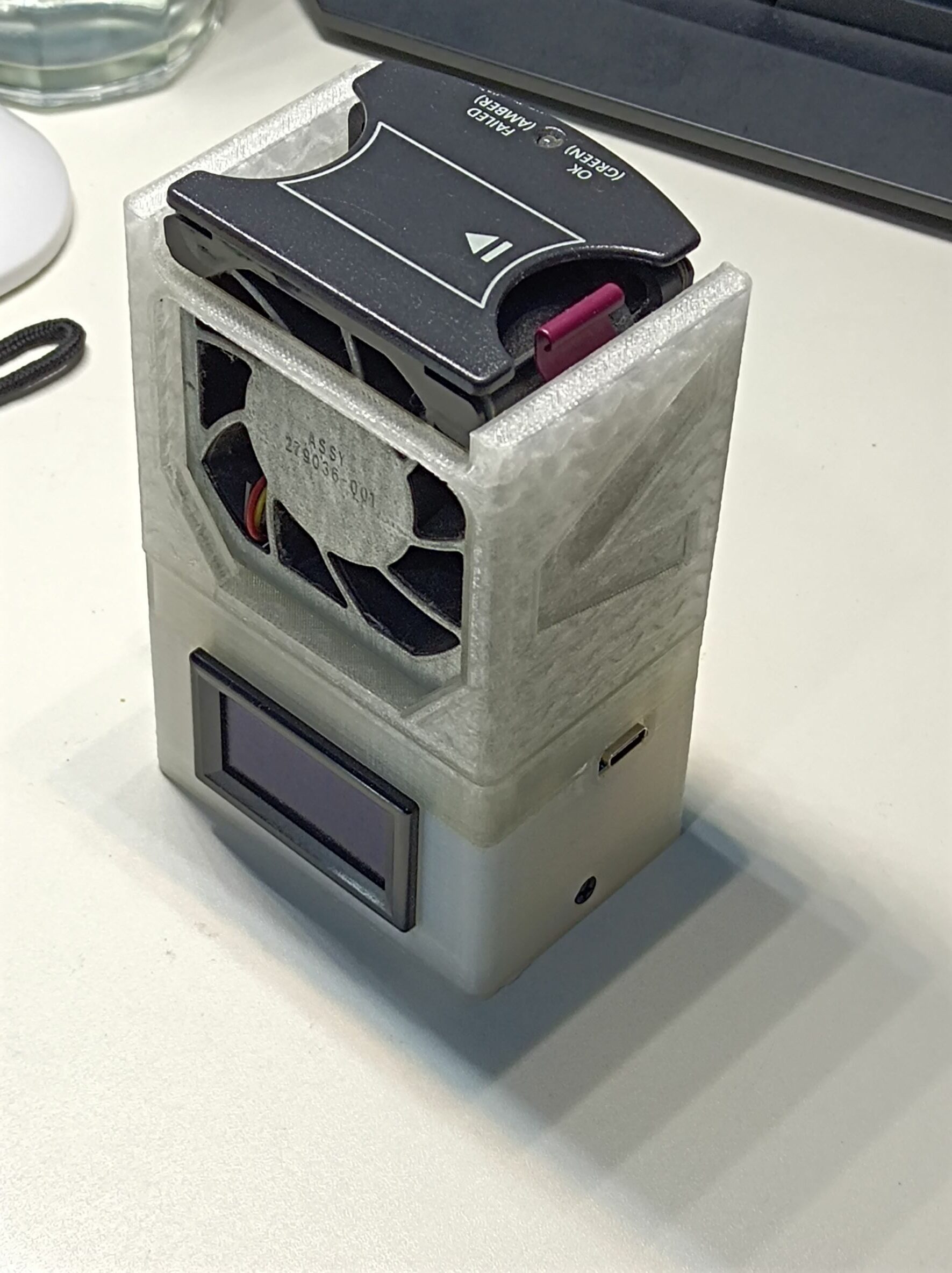
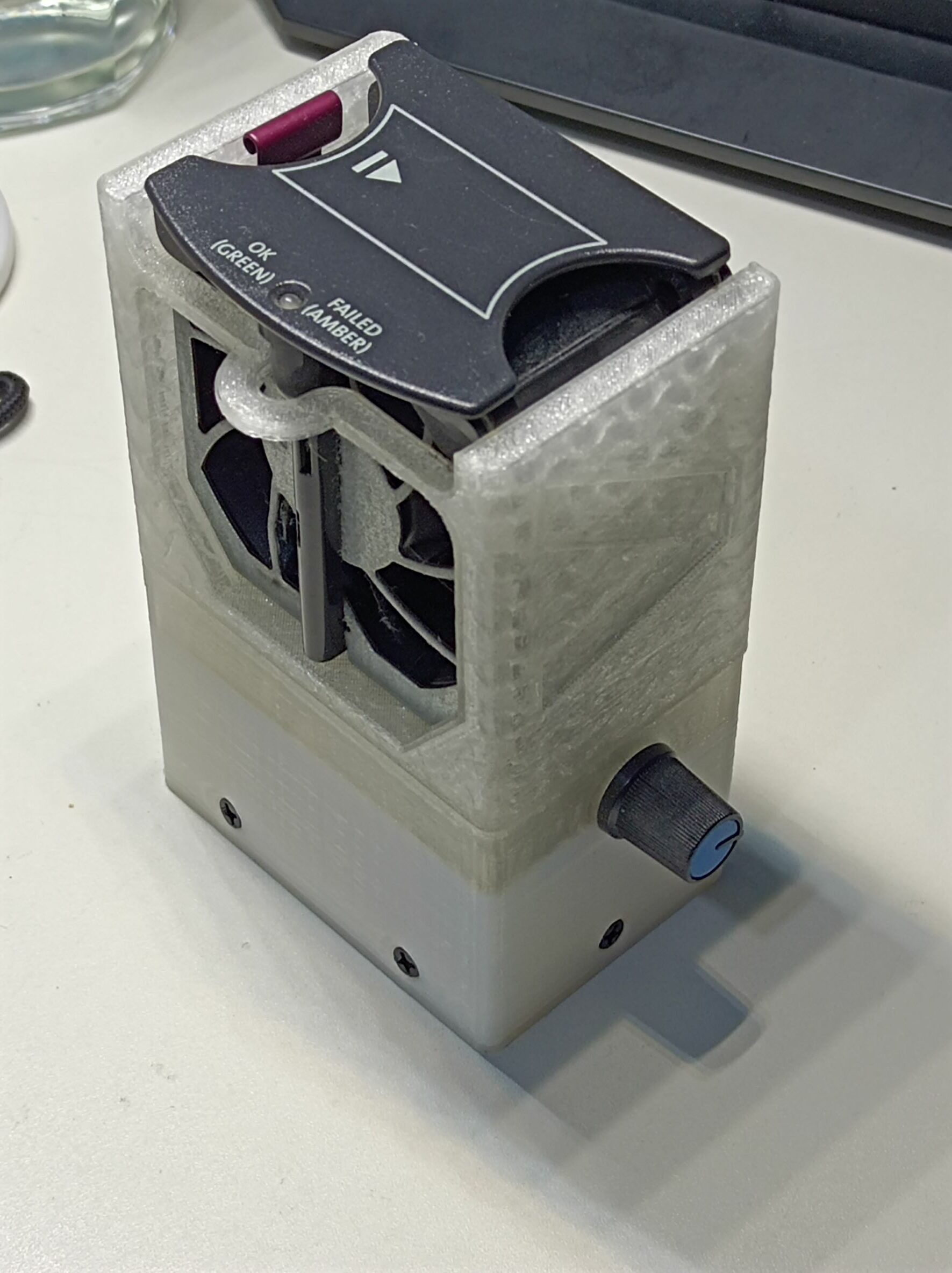
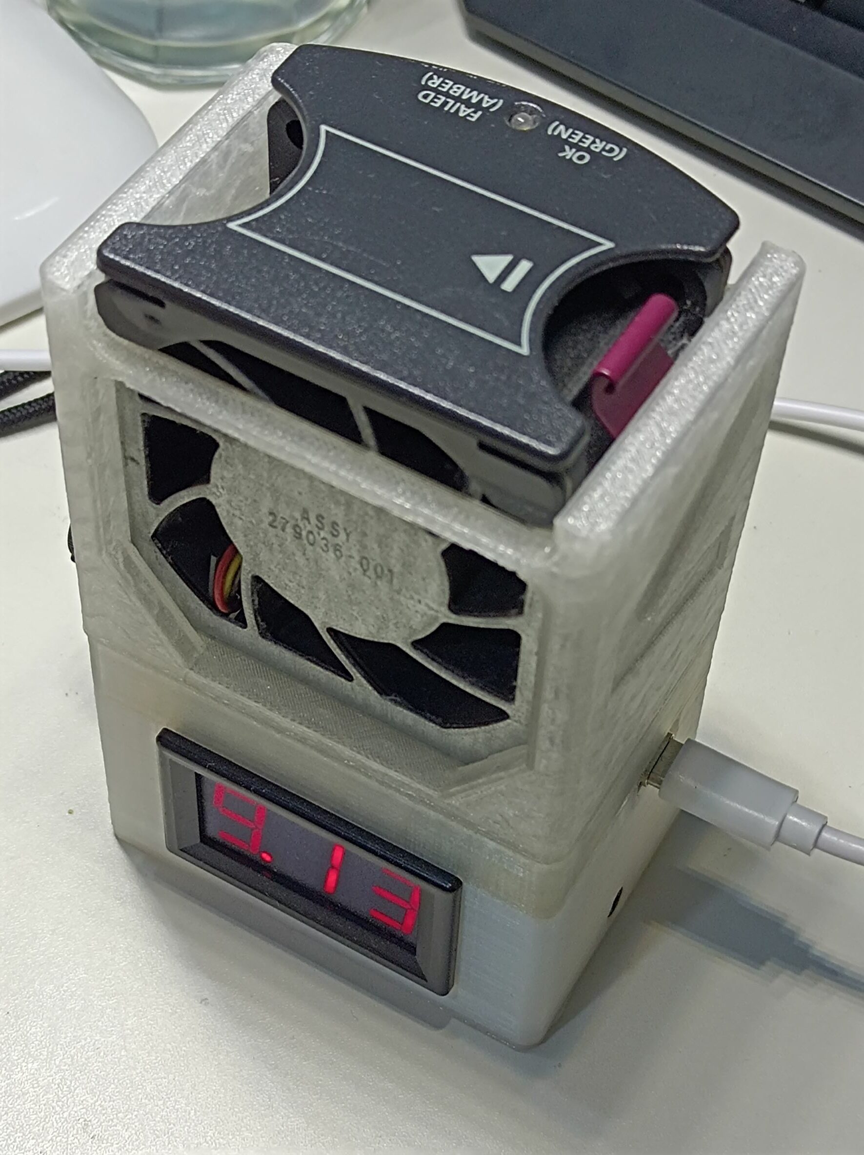
Like with the power supply, during initial testing, I used a server fan in an adapter/base I made earlier, which takes 5V power via a USB port and steps up the voltage. There’s also a POT on the side for adjusting the output voltage, and a voltmeter on the output. It’s shown in the photos below:
On the blade server side, I just had no hard drives or blanks installed and had the fan blowing directly into the hard drive bay openings. This proved to be sufficient even without running the fan at the full 12V, although with no hard drives installed, it’s only good for testing (I ran a live Ubuntu from a USB DVD reader).
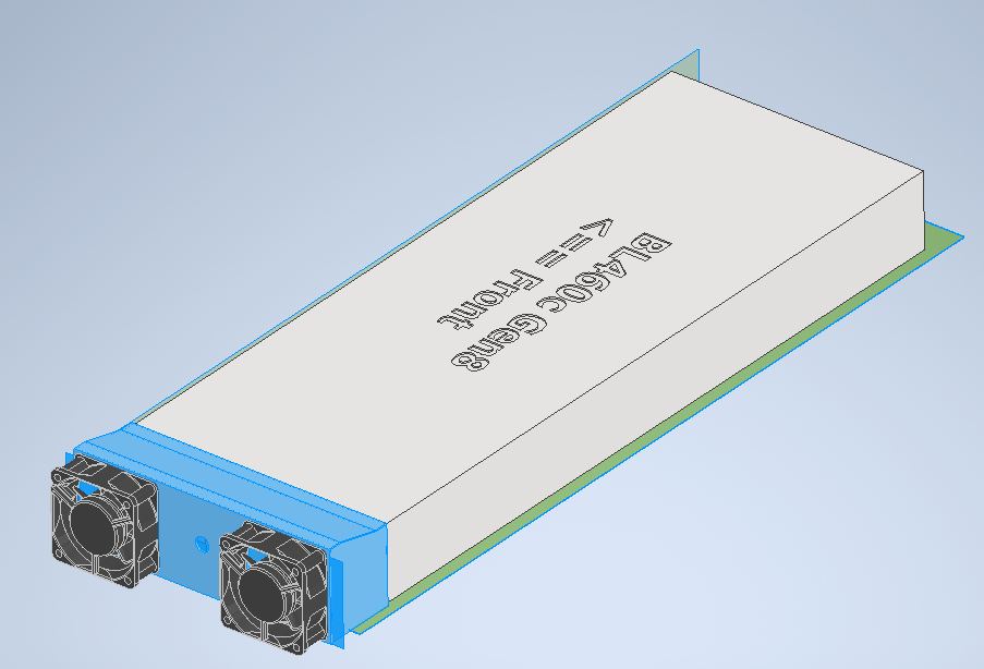
Most people modifying blade servers will cut a large hole on the steel lid and glue or duct tape a 90cm+ PC case fan for cooling, but I wanted to come up with a more elegant solution as I try to avoid destructive mods like this. Once I made sure the whole system setup works, I fired up Inventor and modelled an adapter for two little server fans at the back:
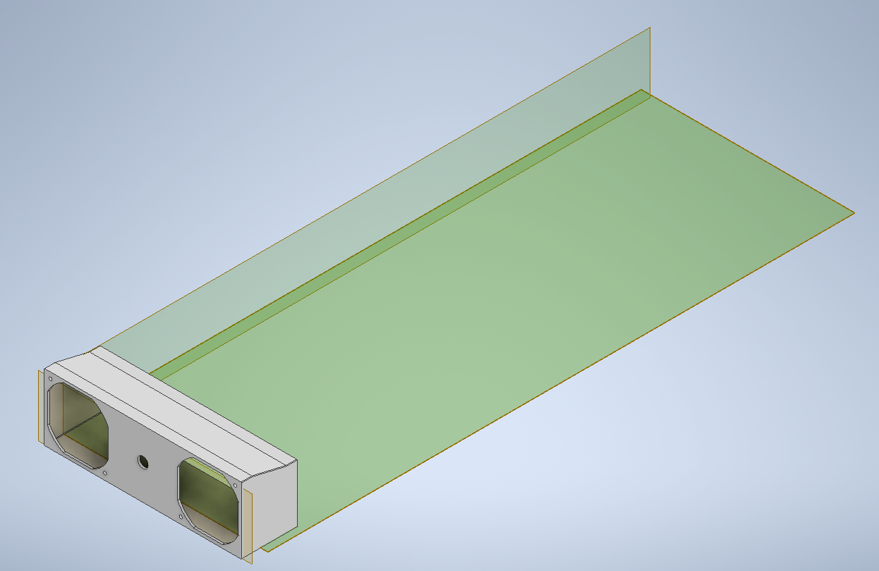
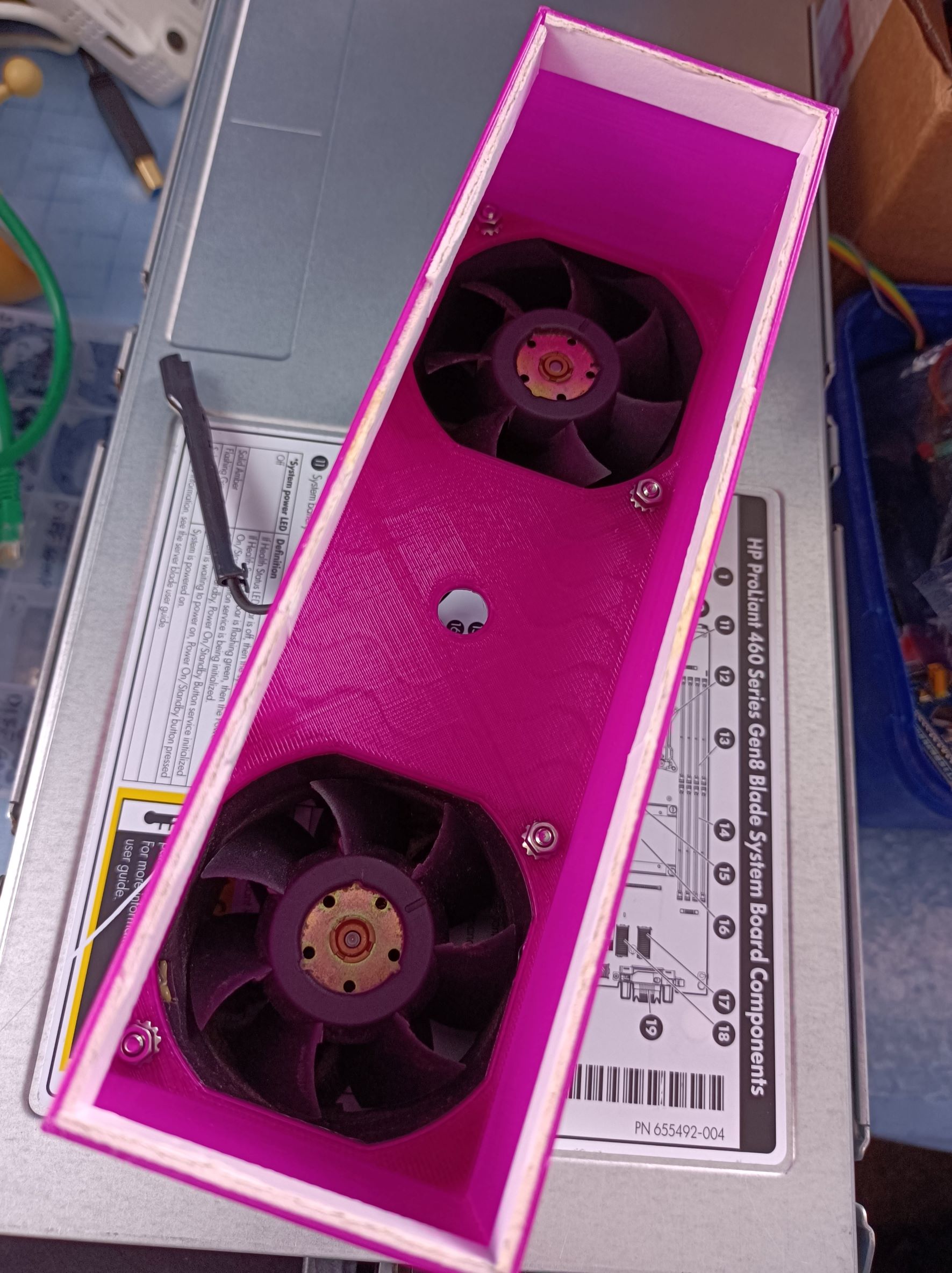
This would fit two of the HP DL380 Gen3/4 fans with their brackets removed (which are standard 60mm fans), like in the following image:
The hole in the middle was supposed to run the power cables and any signal wires, although once this was printed, I had to drill out extra holes for power at better locations. Here’s the adapter assembled with fans:
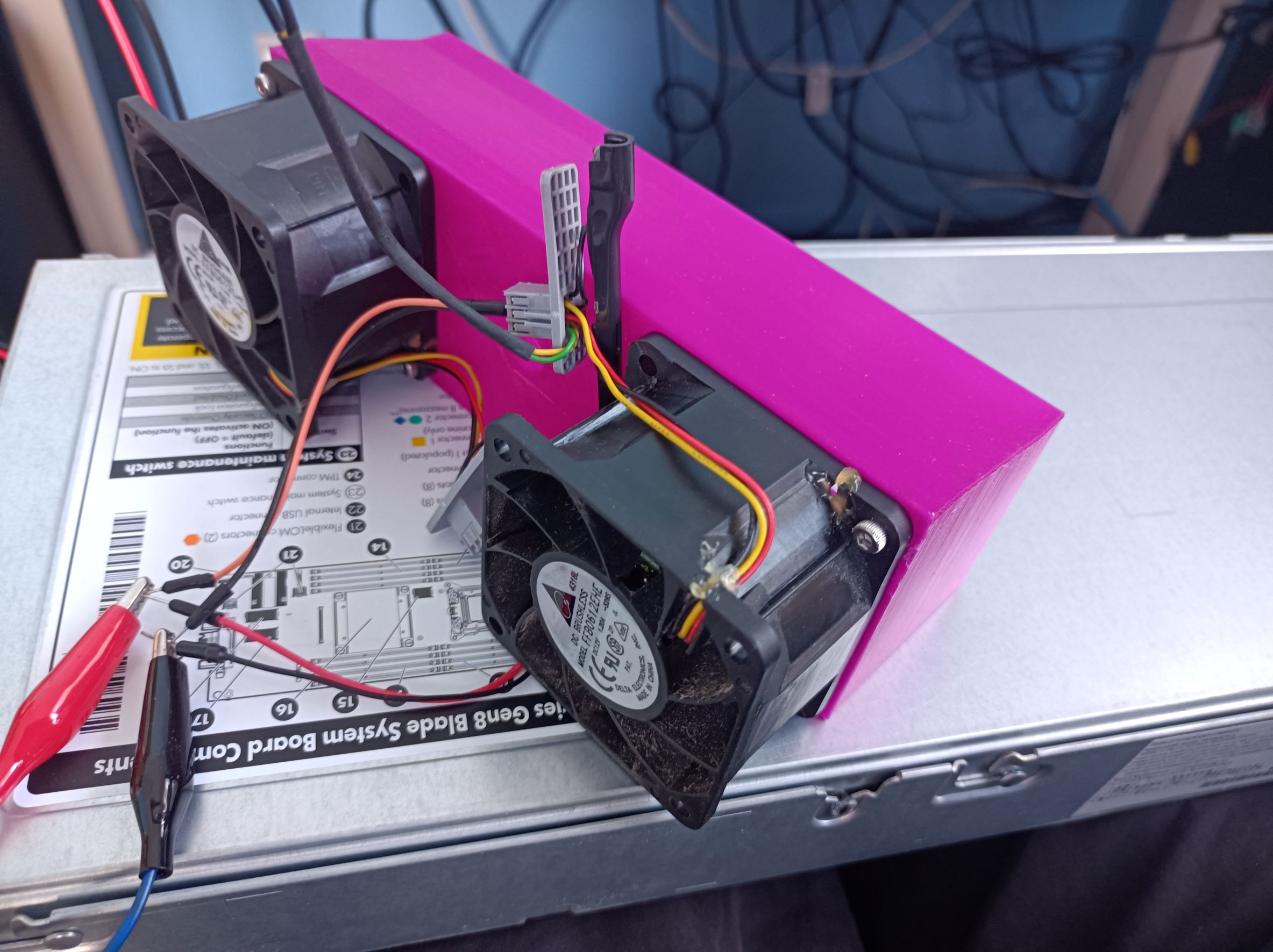
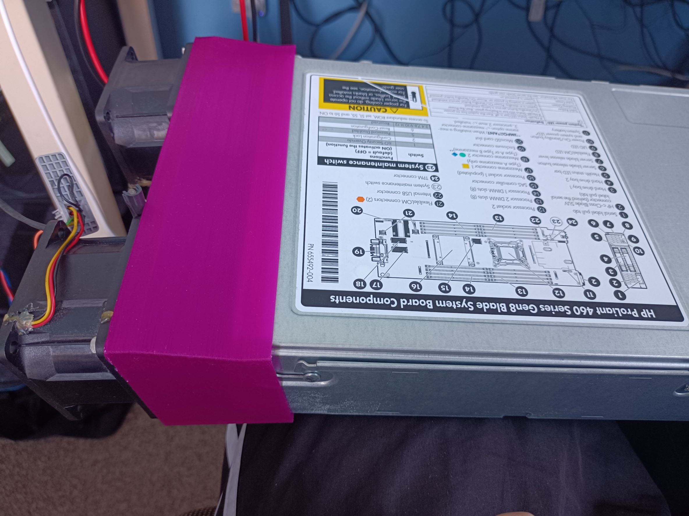
The internal dimensions of the adapter were a little too loose to fit on the back of the blade server, so I lined it with a loop of foam tape. It worked well with a bonus feature of sealing the edges better 😀
In later testing with this, I used a bench supply to power the fans and to set different voltages (as running them at full 12V gets very loud). The server seems to cope well with the fans supplied with 7V, while the hottest spot was near the HD controller, at about 63C. The HP iLO management interface provides an intuitive 3D view of the temperature sensors which made the hotspots really obvious.


Startup
Here is a blog post by a Russian guy who managed to start his BL460c Gen7 by turning switches 1 and 3 to the ON position in the maintenance switch block. There are two switch blocks in the Gen7; While in the Gen8, there’s only one switch block near the front of the server, but the same setup still works!

Display Output and Connectivity
Although most of the connectivity interfaces (10Gb Ethernet, fiber channel, server administration, iLO, etc.) are on the backplane connector, the blade server does have a diagnostic port on its front panel. On BL460c Gen8, it provides a VGA display output, a serial port, and two USB 2.0 ports. The adapter cable is also called the SUV cable, with an HP part number of 409496-001. This allowed me to hook up a monitor, a keyboard/mouse, and USB WiFi/Ethernet adapters, although with it being only USB 2.0, the throughput will be quite limited for networking and file transfer.
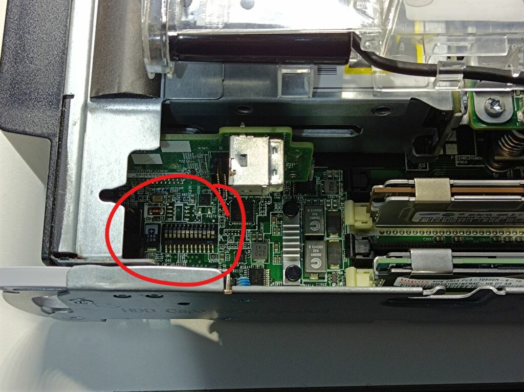
From this video, I learned another trick for accessing the HP iLO functionality on the blade server. iLO stands for integrated Lights-Out; it’s a system with its own little processor that runs independently of the CPUs in the server and provides diagnostic and maintenance functions. It’s accessible via a dedicated Ethernet interface (100BASE-T), which is wired to the top right four pins of the backplane connector. The pinout is as follows:
| Orange | Green |
| Orange-white | Green-white |
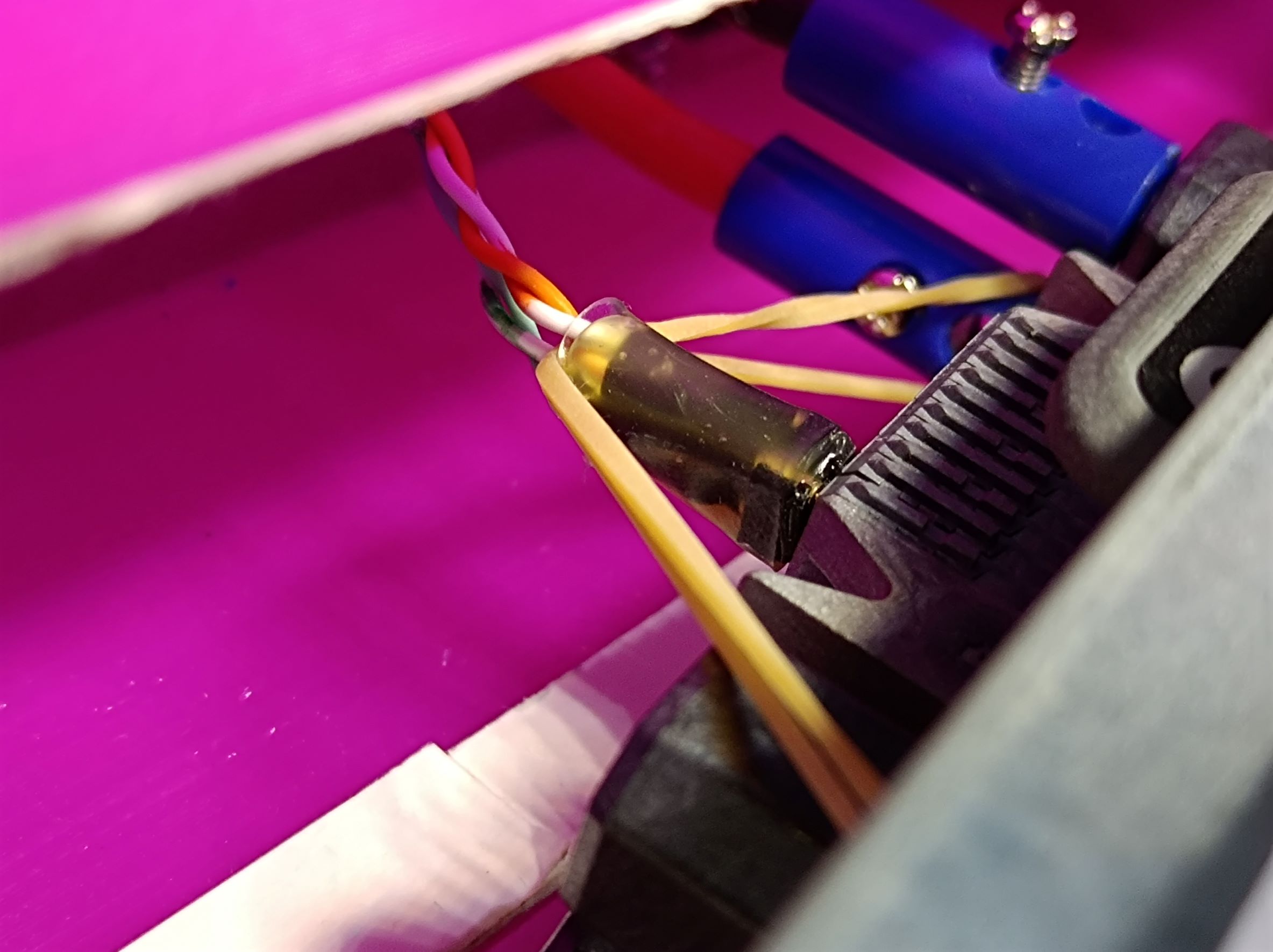
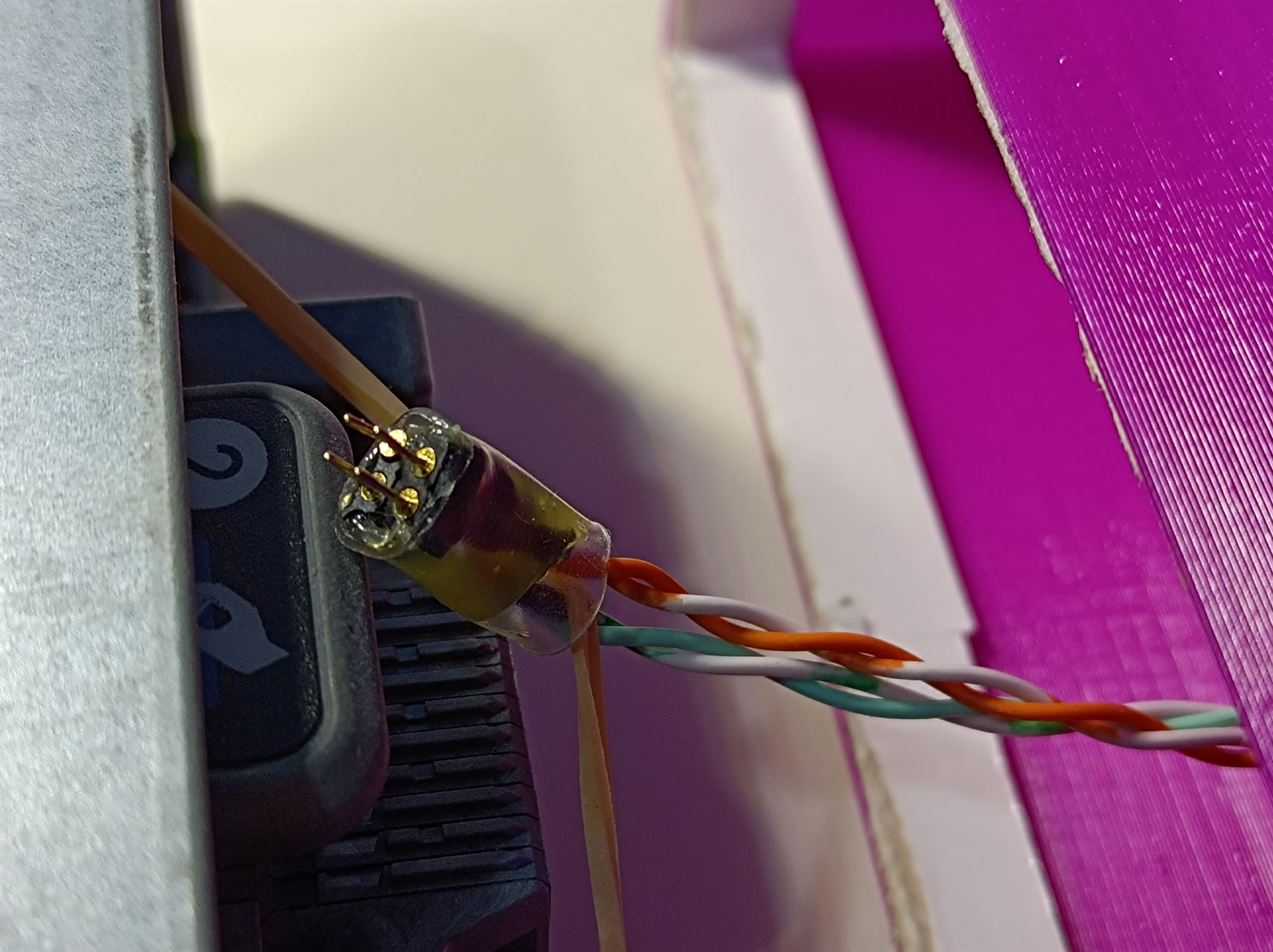
From measurement, the pin pitch of the backplane connector is about 1.9mm, so I used some 2mm headers I had on hand to make a simple 2×2 header block, using hot glue and heat shrink. The pins were a bit short, so I used a small rubber band to make sure the header stays in place.
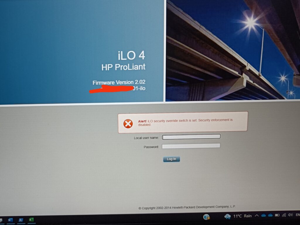
With the switch blocks 1 and 3 set to the ON position, the iLO security is overridden and the default admin/admin credentials can be used to log into the iLO interface:
Completed Setup
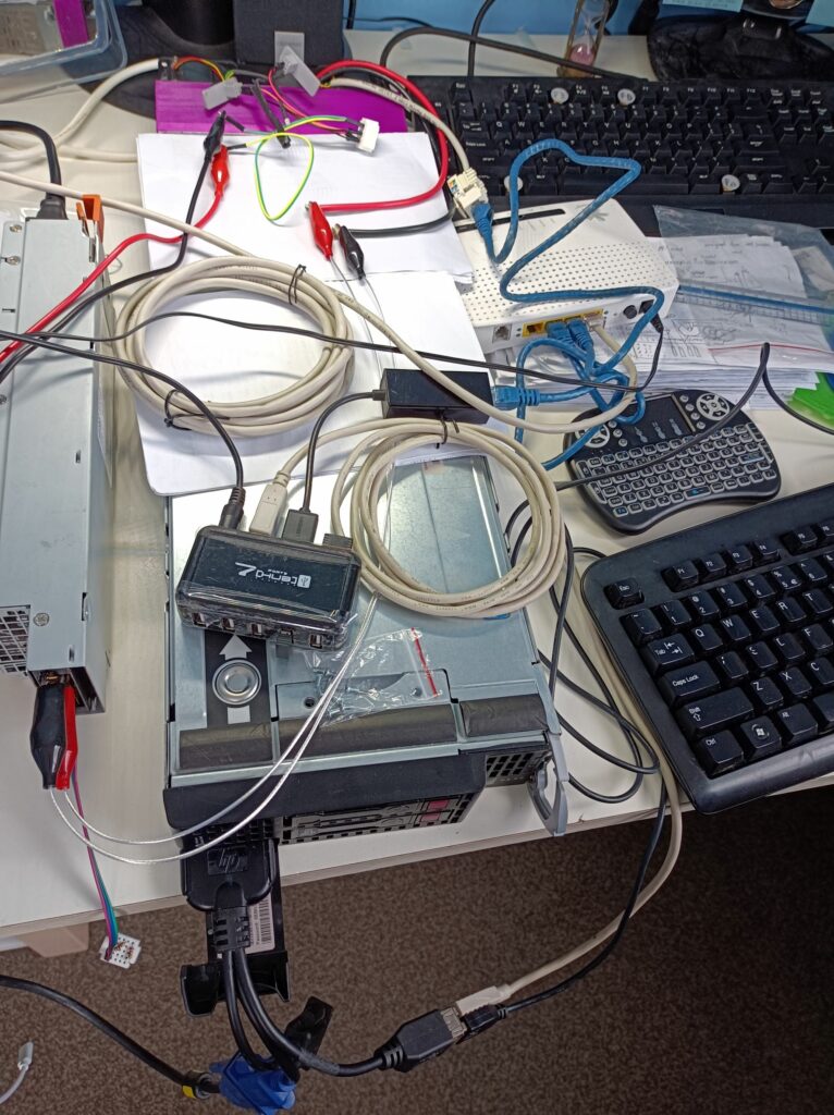
Here’s a photo of the whole system I had on the bench:
Here’s a photo of the htop and hardinfo windows in Lubuntu 20.04:

What’s Next?
Now that I have the system working, I plan to design a simple frame using 2020 Aluminium extrusions and printed parts, so the blade server and the power supply can be neatly organised together. That should make the setup easier to move around just like a desktop PC, as I plan to put it away when not used.
Hi
ich selber hatte noch kein BL 460C G8 sonder ein G7 mit dem ich eine eGPU angeschlossen habe. Später hatte ich auch mal ein BL 660C G8 bei dem ich ebenfalls PCIe genutzt habe für eine Netzwerkkarte. Wollte dann mal schauen wegen der interne 10Gbe ob man da ich irgendwie anzapfen kann wie bei dem ILO. Ich schaue derzeit nach einem G9 dieser ist sparsamer und schneller.
Hi Andreas, did you manage to get the onboard PCIe out to an eGPU? That’s pretty impressive to me. Did you modify a mezzanine card to get those PCIe lanes out? This is something I’ve thought about but never tried.
I have traced the hardware connections from the NIC connector and found that there are a total of 16 lines that go from the mezzanine connector to the backplane connector. Maybe that’s 8 SerDes lanes? This is completely outside of my current knowledge, unfortunately. I would also think the way I wired the iLO won’t satisfy the signal integrity required by 10GbE signals.
I tried to look for the part number of a matching backplane connector (for better signal integrity) with no success.
I also have a G9 – haven’t modified that yet!
Yes, the onboard messanine only tested it with 1x PCIe. Desoldered the connector of the mezzanine card and directly connected a “USB 3.0 cable”, as used for the mining cables. Had also measured the blade committee for the mezzanine card and the network card, but 3-4 years ago I have to see if I still gave away my documents from the measurement of the BL660C G8 because it simply drew a whopping 600W and there is electricity in Germany is particularly valuable and expensive. Originally I also wanted to buy a backplane to measure the pin assignment, but it was expensive.
Electricity is also pretty expensive here in New Zealand, so I just use it as a PC/workstation rather than a server. Is there any chance you can share your connections for breaking out the PCIe lane from the mezzanine connector?
I also saw two used C7000 chassis with blades pop up in the local market, but they were sold as a whole and weren’t particularly cheap either (plus they’re sooo heavy) so I didn’t go for them.
Für mich war der BL-460c G7 wie ein Kleines ITX System und das reisen C7000 System würde alles groß und schwer machen. Das C7000 gibt es oft recht günstig ich hatte Monate lang geschaut nach einem C3000 nicht für das 19“ System sondern mit rollen wie ein Desktop, ist aber leider sehr selten und wenn sehr teuer! Habe mal sogar ein Video gemacht mit ILO und PCIe am BL660c G8 aber habe es nie hochgeladen. Bin eigentlich nur auf das Blade System zurück weil es jetzt endlich HP G9 Systeme billiger gibt. Wenn ich es gefunden habe, wie kann ich dir Bilder senden?
I can read english but don’t write so I use a translated one but forget to translate before posting. I found pictures of the mezzanine connector for G1 – G7, but G8 at the moment only a video in which you can see the mezzanine connector to PCIe but the pinout would be difficult to replicate. I bought a BL 460C G9 to test.
I can send you an email from my address for photos. Yeah the C7000 is very heavy and big, and my intention of getting one was solely to make measurements on the backplane, to figure out how to wire up PCIe etc. Therefore I’m not willing to pay much at all for two C7000s (two is even less desirable because I also need to figure out transport and disposal). I’m pretty interested in your video! Look forward to it.
Hello. It’s been a long time, but tell me, did you manage to figure out the pinout of the rear connector of the BL460C? If you did, could you share the pinout? I have gen 6, I managed to connect iLO according to your manual. But as far as I understand, there is also Ethernet and PCI-e
Hi Geban, unfortunately I didn’t progress further with figuring out the backplane connector pinout, as USB2.0 via the front port and remote desktop was enough for me to use as a local computing node. Yes the backplane connector also has Ethernet and PCIe but they require the right connector, which I couldn’t find in my search. Besides that, I imagine they will have high requirements for signal integrity to work so flywires probably won’t be good enough (will need some custom PCB with the right connector).
I have tried the same setup you suggested in your blog but everytime i plug the power. The blade server health light flashed RED with 1 long red and 2 short red flashes. I have no idea what is the cause of that. Do you have any idea what could be the issue.
Along with RED health flash i have noticed a light on the motherboard also flashed green near rear CPU called R7.
Let me know if you know anything about this issue.
Hi Nitin, I didn’t encounter this issue and the only thing I could think of (other than a true hardware fault with your blade) is your power supply. Is it capable of delivering say at least 15A? Do you have thick cables and reliable connection between the blade and the PSU to guarantee a stable power to the blade?