In a previous post, I wrote about getting an HP server blade and getting it to work without a blade centre. In this post, I’ll document what I did to turn the setup into a self-contained PC.
Chassis Build
Firstly, I needed to house everything together in a strong enough structure. I chose the 2020 Aluminium extrusions as they’re strong, versatile and relatively easy to process. I had some experience with them when I put together my 3D printer and installed custom modules, so I was familiar with how they work. With that said, I haven’t designed anything with them from the ground up, so it was also a learning opportunity.
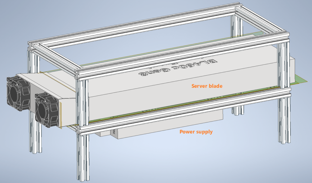
In my design, the Aluminium extrusions form two levels, with the lower level holding both the power supply and the server blade, and the top level just for stopping the blade from sliding laterally. I used simple butt joints for the extrusions to simplify cutting and allow the reuse of these extrusions in the future if I need to. As the lower platform will take most of the weight, I had it sit on the bottom vertical pieces so the joints aren’t bearing the weight.
Originally, I planned to use 3D-printed joints for everything to save cost, as with something this small, the cost of metal joints would get close to the cost of the extrusions themselves. With that said, they’ll never be as strong as the metal joints. In the end, I chose a mix of metal joints for the main load-bearing points and printed joints for the rest to save some cost.
Once I had a basic concept of how the pieces will come together, I found a 2020 extrusion model from GrabCAD and modelled how the beams will join in Inventor:
After confirming the sizes of the extrusion pieces, I ordered some 1.5m beams and got them cut at a friend’s place with his mitre saw. The lengths are as follows:
| Extrusion piece | Length (mm) |
| Vertical | 100 |
| Left-right | 180 |
| Front-back | 500 |
I chose the length for the left-right pieces to be the same as the server blade, so I can adjust the width of the frame for a tight fit while accounting for any measurement/cutting inaccuracies. This does mean the left-right pieces won’t be touching the front-back pieces directly when the fan adapter is on the blade (as that widens the server by ~2mm), which made assembly of the frame a bit tricky to keep everything square. I would probably do it differently if I were to do it again…
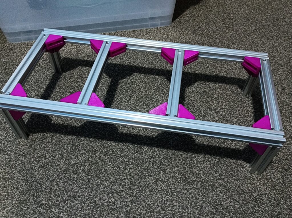
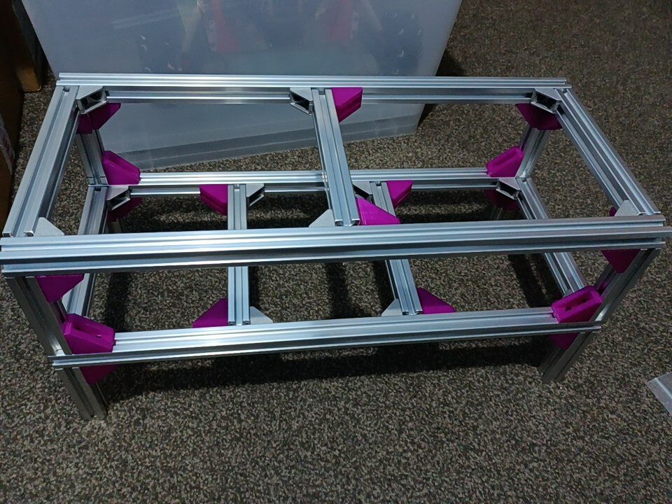
Here’s the frame assembled with just some 3D-printed corner joints, and with a mix of metal and printed joints:
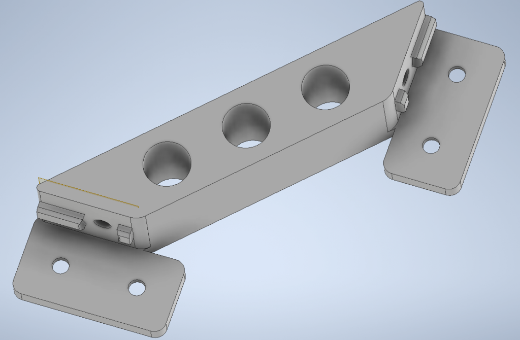
I designed the corner gussets in a shape similar to the common aluminium counterparts but with much thicker walls. It’s designed to fit M4 screws and seemed to work okay when I just printed them in PLA. Being plastic, they won’t have nearly as much strength as the metal ones (even with thickened walls) but would do for my purpose. Here’s the model, both as an Inventor part and as an STL file:
I also modelled a larger piece after a Thingiverse model here – the original model seems to have some mesh problems when imported into my Cura slicer, so I just remodelled it:
It’s sturdier than the corner gussets, but it uses more screws (6 instead of 2) and takes much longer to print, so in the end, I didn’t go with this for joining the extrusions.
Cooling Mod
Fan Adapter V2
In the previous post, I had the power wires coming out through the fan adapter, between the fans. This approach had two problems – first, the holes need to align well with the power sockets on the blade, but the complex shapes at the back of the server made it tricky to measure their locations accurately. Sure, I could make the holes on the adapter larger to accommodate bigger measurement errors, but then it becomes leakier for cooling. Second, running the wires through the fan adapter makes everything (cooling, power, iLO wiring) all coupled together mechanically and is just harder to put on and take off any one of them.
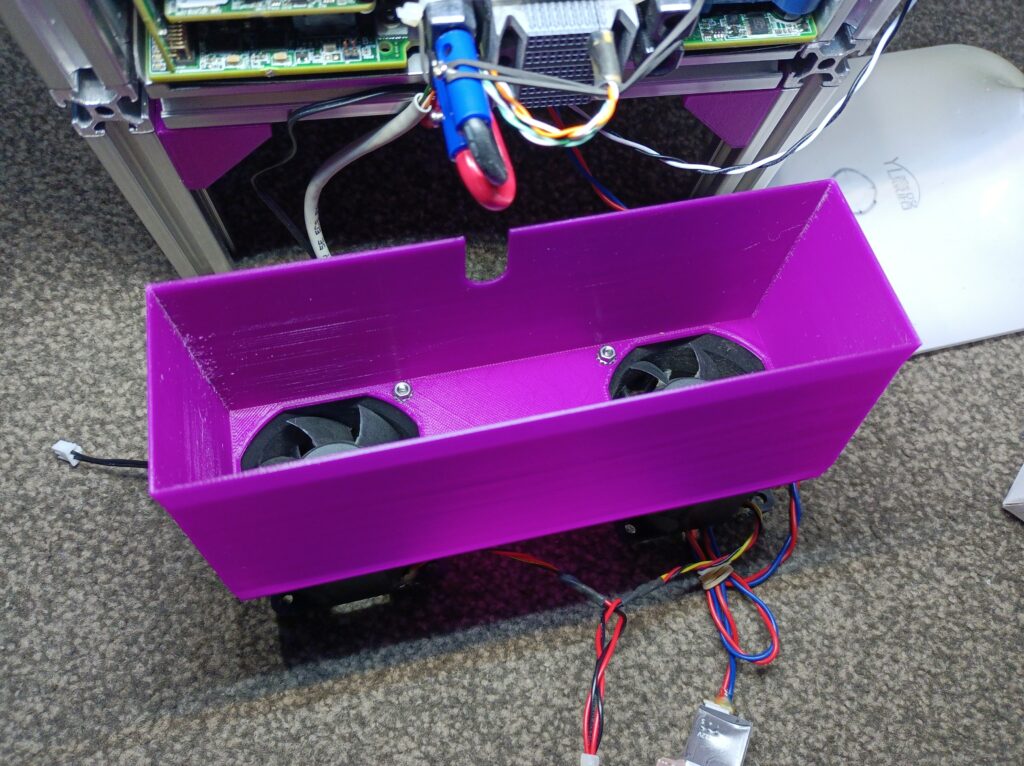
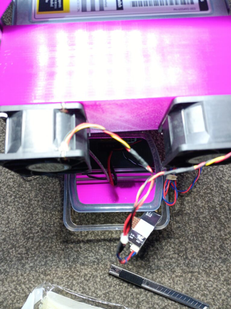
My solution was just to make the fan adapter slightly longer (adaptive modelling comes in handy here – just change one distance parameter and the model updates) and let the cables take a P-bend as in the following image. This would remove the need for measuring the power socket locations and decouple the cooling with the cables, making installation/maintenance easier. I only needed to add a cutout in the fan adapter model.


Here’s the model for the fan adapter:
Fan Controller Mod
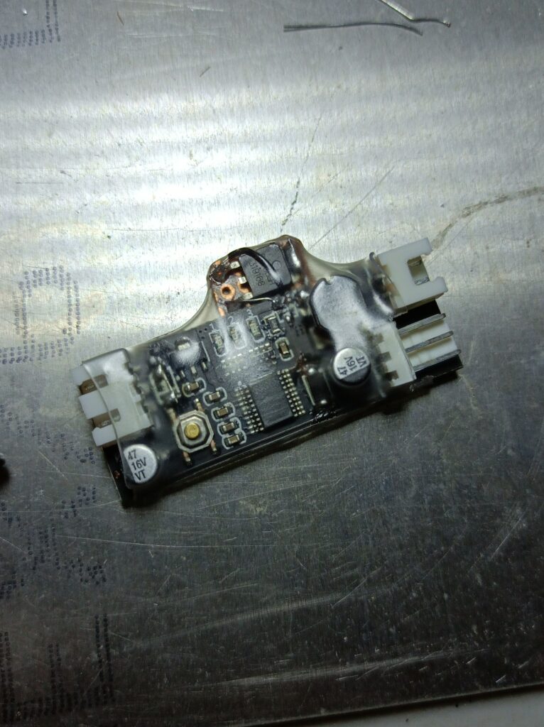
As the fans on the fan adapter are server fans, they get really loud if given the full 12V power. Wiring them directly to 12V is certainly not desirable if I wanted to use the setup as a PC. Previously, I bought some fan controllers that take a thermistor input and installed one in my T3600 desktop for the CPU fan (with the stock BIOS and Windows 10, the fan always stays at the minimum speed no matter how hot the CPU gets). Here’s a photo of the fan controller:
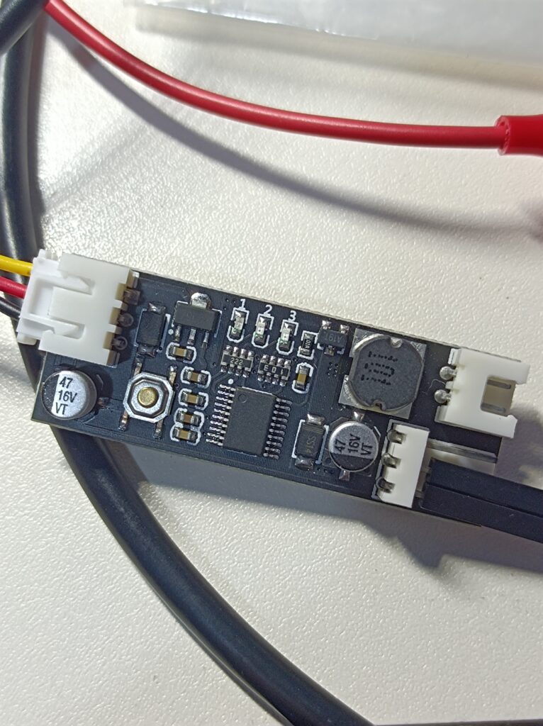
This fan controller uses a buck circuit to change the output voltage going to the fan, changing its speed based on temperature. It’s better than the ones that simply generate a PWM speed control signal, as it could turn off the fan completely and works on virtually any fan. The server fans I’m using don’t support PWM speed control, so changing the fan voltage was necessary. It also has a user button and three LEDs for setting the temperature profile and displaying its current state.
There was a problem though – their maximum rated current was only 0.8A, and the server fans are rated to take up to 2.4A when running at 12V, so some modifications are required. After some quick reverse-engineering, here’s a basic schematic of the fan controller:
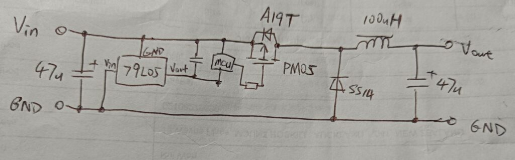
This fan controller also passes through the tachometer signal of the fan, requiring the input and output lines to share a common ground. I think how it handles the PMOS driving is quite clever here: a negative voltage linear regulator (79L05) is used to generate a power rail 5V below the +12V input line. Its output line is then used as a floating ground for the microcontroller, which reads the temperature and generates the appropriate PWM signal for the MOSFET. This arrangement allows a simple, direct connection between the microcontroller and the MOSFET gate, as when the MCU outputs a logic low, the MOSFET will see a -5V gate-source voltage, turning it on. When the MCU outputs a logic high, Vgs would be 0V, turning it off. There is also no output voltage or current feedback (as it doesn’t really need one), making the whole system very simple and low-cost.
The main components that limit the current capacity of the module are the MOSFET, the inductor and the diode. There’s also an input reverse-protection diode, which I don’t need in this case (the supply will be permanently wired). A quick search for the A19T MOSFET reveals that it has these parameters (datasheet here, or here):
| Vds (max) | -30 | V |
| Id (max, continuous) | -4.2 | A |
| Rds(on) @ -4.5V | <75 | mΩ |
| Vgs(th) (Typ) | -1.0 | V |
| Ciss (Vds=-15V, Vgs=0V, f=1MHz) | 880 | pF |
| Qg (Vds=-15V, Id=-4.2A, Vgs=-4.5V) | 8.5 | nC |
The next size up MOSFET I had on hand was the AP6679BGH, in a TO-252 (DPAK) package. Its key parameters are as follows (datasheet here, or here):
| Vds (max) | -30 | V |
| Id (max, continuous) | -63 | A |
| Rds(on) @ -4.5V | 15 | mΩ |
| Vgs(th) (Max) | -3.0 | V |
| Ciss (Vds=-25V, Vgs=0V, f=1MHz) | 3500 | pF |
| Qg (Vds=-24V, Id=-30A, Vgs=-4.5V) | 44 | nC |
As shown in the tables, the AP6679 has a much higher drain current rating, although also a much larger input capacitance, which might affect the gate waveform, degrading the overall efficiency. Still, probing reveals that the controller runs at 50kHz, which is not very high. The gate resistance used on the original controller was 100Ω – I just replaced it with a 10Ω resistor and the plan was to probe the gate waveform afterwards to see if it looks okay.
The SS14 diode is a common Schottky diode rated for 1A and 40V reverse breakdown. I replaced it with an SS34 (3A 40V) and shorted the input reverse protection diode. As for the inductor, I didn’t have anything that was only slightly larger unless I make a custom one, which I didn’t feel the effort would be justified. Again, the plan for the inductor was to try and see if it works. Here’s the module again, with the modifications explained above:
Once I put it back together and tested it with a 2A load, it worked! The output voltage waveform wasn’t very clean, but I think that would be mainly due to the small output capacitors and the low switching frequency. The fans still worked across the entire speed-setting range. Here’s the gate waveform of the new MOSFET (referenced to ground), which wasn’t bad (shown below). The heating of the inductor was also acceptable.

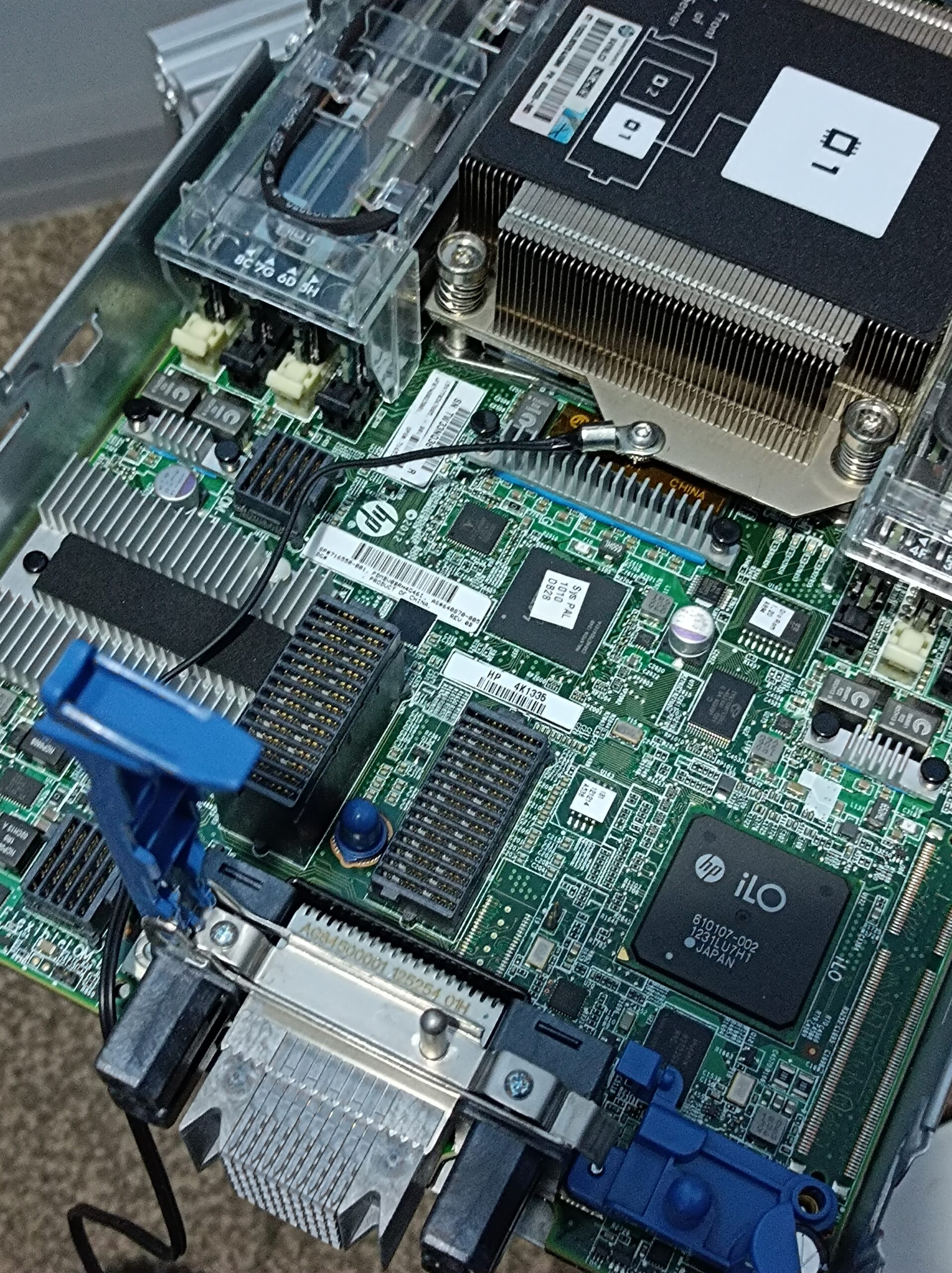
As for the thermistor attachment, the fan controller module comes with an NTC lug thermistor, sized M3. There happens to be a place on the heatsink block of the rear CPU that is a thin sheet of (Aluminium?) and is cleared of nearby objects. Placing the thermistor there also wouldn’t really impede the cooling airflow. An ideal place, really. Below is the heatsink, with the lug thermistor installed:
Once it’s all put together, I configured the controller to idle the fan at 20% of the full output, the temperature at which the fan speed increases was set to 40 ℃, and the temperature band in which fan speed gets gradually increased to maximum was set to 15 ℃ (i.e. the fans will reach full power when the thermistor is 55 ℃ or higher).
Power Supply Connection
In this build, I used the same AA23260 power supply as documented in the previous post. I’m never really comfortable soldering directly to the contacts in connectors, so I took it apart and soldered the output and control wires on the connector pads as shown below. The joint may look dry, but the solder did wick through all the individual strands of the wire and made proper contact with the pads below.

Lastly, I designed a little mounting tab for an 8.5mmx13.5mm rocker switch, controlling the enable lines of the power supply:
Putting It All Together
The first step I took in the overall assembly was to attach the power supply to the lower level of the frame using cable ties:
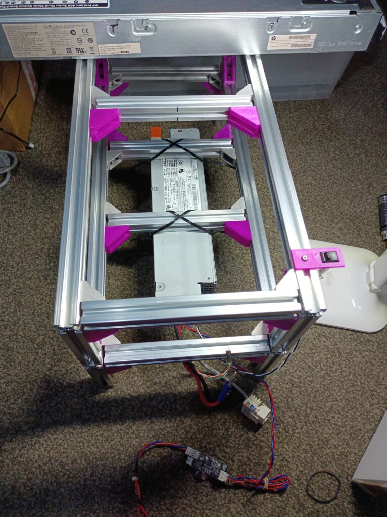
I did consider designing some printed brackets for holding the power supply, although I figured the time required probably doesn’t really justify it. It’s a one-off installation, and if this breaks, I would be using some other server supply that would have a different geometry anyway.
Next, the server is slid on top of the first level and the wires are connected. Originally, I planned to have the fan adapter stay in place just by the weight of the server blade. It turned out the two server fans are too heavy for the 1mm printed PLA walls, which cracked after sitting there without extra support for a couple of weeks. In retrospect, it was a big cantilever for the printed thin walls to handle. As a quick workaround, I strapped a piece of cotton string from the fans to the aluminium extrusion. A better solution might be some kind of platform made using laser-cut acrylic, printed brackets or more extrusions pieces. Or maybe the front-back extrusion pieces could’ve been made longer.
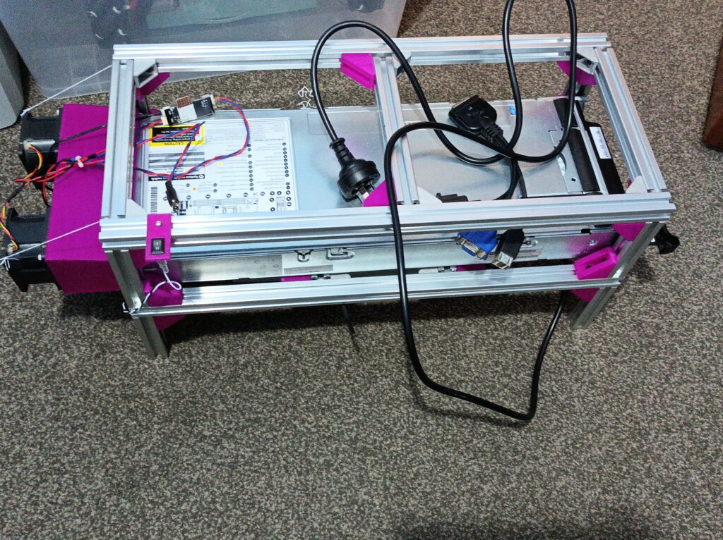
As shown in the above photo, I also added a DC barrel plug from the 12V line intended for powering auxiliary devices, like a USB hub.
Quick Thermal Testing
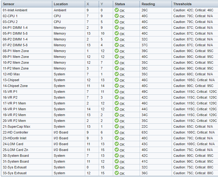
Lastly, here are some thermal test results. The fan controller was set to increase the fan speed above 40 ℃ and will reach the full 12V output at 70 ℃. To get the idling temperature, I let the system boot to Windows 10 and sit idle for at least half an hour to reach thermal equilibrium. The system seems to idle at about 130W with dual E5-2620 and 16x 8GB DDR3 1333MHz RAM. Through the iLO interface I can see the highest temperature is at “22-HD Controller”, which is 63 ℃:
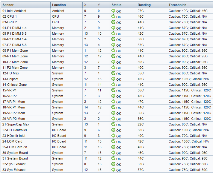
I then used the Base mark Web 3.0 online tool to push the CPU load up, increasing the power to about 190W. The CPU usage got up to about 80% on all cores. Now the hottest spot is still the RAID controller, although with increased airflow, its temperature has dropped slightly. After 15 minutes, the hottest spots are the sensor “22-HD Controller” (the RAID controller) at 58 ℃ and the sensor “15-VR P1” (voltage regulator module for CPU 1?) at 56 ℃. The CPU temperature remained under 50 ℃, which is what the fan controller is sensing. I’ll say the cooling system works pretty well!
Other Testing and Running Notes
Without access to the backplane PCIe bus or the onboard NICs, the best networking speed I’ve achieved with the “blade PC” was 320Mbps, using a USB 3.0 to GbE adapter connected to the SUV port. Since the theoretical maximum speed of USB 2.0 ports is 480Mbps, I think 320Mbps is pretty decent!
The best resolution supported by the onboard GPU seems to be 1280×1024 – this was the best I could select when connected to a 1080p monitor. When I connected using Windows RDP, there didn’t seem to be such limitations, and I was able to display the remote desktop on two 1080p monitors.
I’ve also set up the system twice on two system drives (one with Windows installed and the other with Ubuntu installed) that I can swap in or out when there’s a need to run something natively in Windows or Linux. I have the two onboard drive slots configured as two logical volumes each mapped to a drive, effectively bypassing the RAID card. After changing the disk between boots, the RAID controller would prompt that the drive has changed. Pressing F2 would tell the controller to accept the change and proceed. If no action is taken, the controller would disable the drive as a fail-safe mechanism, and the system won’t boot. The default timeout is 45 seconds, so there is no need to rush.
Another catch with the RAID controller is that it seems to take a few seconds to get power (maybe it’s charging the cache capacitor?). If the power button on the blade is pressed straight after the 12V power is enabled, the RAID controller won’t turn on (no lights), leading to a “no operating system disk” type of error after POST. Simply waiting for a few seconds before turning on the blade seems to reliably get around this problem.
Conclusion
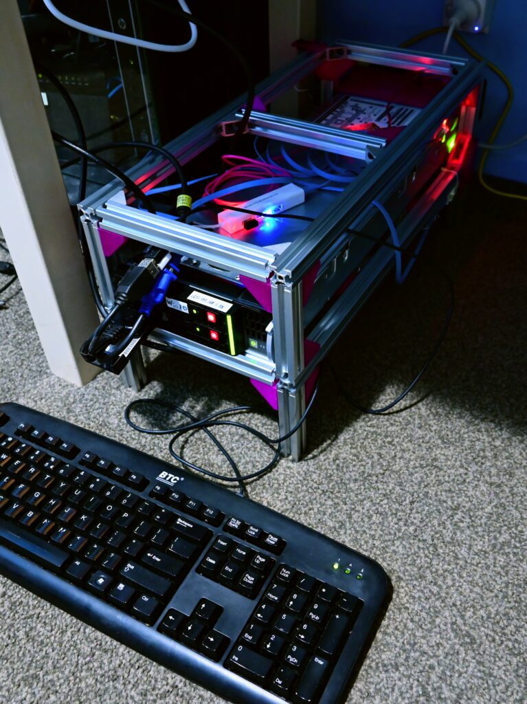
So here it is, a working PC sitting under the desk that doesn’t sound like a jet engine 😀 It is still louder than a typical PC (mostly contributed by the server power supply), but so much better compared to some old rack-mount servers I used to play with. It also only cost me only ~$200 in materials, which I think is pretty good for the result!
Update Jun 2023: I’ve continued to use this machine on odd occasions. The CPU got upgraded to dual E5-2680v2, and now I may get occasional blackouts (bad connection at the banana plugs?) when the machine was warming up. Once it’s hot and the temperature settled, I don’t seem to get power-related issues. Now the CPU power reaches 77~80 ℃ under full load. Another issue I noticed is that since the second reboot, the CPU usage reported in Windows Task Manager will get stuck at 0%. Running the HWiNFO tool just once in sensors mode fixes this somehow (maybe some device gets initialised properly when HWiNFO opens the sensors window).